Adrian Zamudio and David LaFehr
For our final project, we created a Roomba-based Pokémon Go application. We built a system of hardware and software modules that enable a Roomba to catch any number of Pokémon that lie on a surface. Should the Roomba stray from the appropriate trajectory, it is quickly redirected to the proper path. Position and quaternion data transmitted from a server over WiFi, in conjunction with Hololens, enable this error correction, which is relatively successful given the limitations of our setup.
Hardware Setup
The hardware setup consists of an Arduino Pro mini connected to a BNO055 IMU sensor mounted on a PCB. This board is mounted on an iRobot Roomba, carefully positioned such that the sensor is at the center of the Roomba in order to ensure accurate sensor readings relative to the center of the Roomba. A Microsoft Hololens, which will increase the robustness of position estimation, rests on top of this. It is important to go through the Hololens startup/initialization process with the Hololens at the same orientation as how it will be placed on the Roomba. The Hololens and Arduino are connected via USB to an Intel NUC. The NUC has antennas which are placed on the same board as the Arduino; these are used to transmit data. Meanwhile, a computer is connected to the Roomba via USB to control the Roomba using serial communication.
Software Setup and Data-Process Chain
The following diagram shows how data is transferred with our software in our design based on the hardware setup described above:
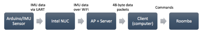 The Arduino is programmed to receive data from the IMU sensor. The code for the Arduino is identical to that which we created for our labs. It is designed to receive the accelerometer and quaternion data from from the IMU, encode the data since they are floating point numbers, and send them to the WiFi transmitter. The WiFi transmitter (NUC) runs a C program to receive the IMU data via UART from the Arduino. This C program is also identical to the software we created for our lab. It is structured such that it stores the sensor data it receives into a buffer, and then transmits to the AP via WiFi. The AP calculates CSI between itself and the transmitting target (the antennas of the NUC), with the Hololens helping with the positioning data. The AP also polls a socket to obtain IMU data being transmitted in WiFi packets. AP and CSI data is then sent in a packet to a server. After this, we do everything from our computer.
For interpreting the data and controlling the Roomba, we use python. We create a server client that establishes a socket connection to the server. We send the MAC address from the target device (NUC), and then receive a port number to listen on to obtain data. We connect the local host to this port, and receive data from the server. The data is 48 bytes long, consisting of timestamps, position x-y-z data, accelerometer x-y-z data, and quaternion w-x-y-z data. Our application requires only position x-y data and quaternion data. We receive new data periodically when we need new readings. Now we have the data we need to control our Roomba!
Methodology
For our implementation, the Roomba travels in straight lines that are perpendicular or parallel to each other – going from one Pokémon to the next, the Roomba travels in a path shaped like the letter “L” (though if two consecutive Pokémon have the same x-coordinate or y-coordinate, the path is simply one straight line). We chose this strategy because it allows for easier determination of the accuracy of the Roomba’s trajectory relative to the given trajectory.
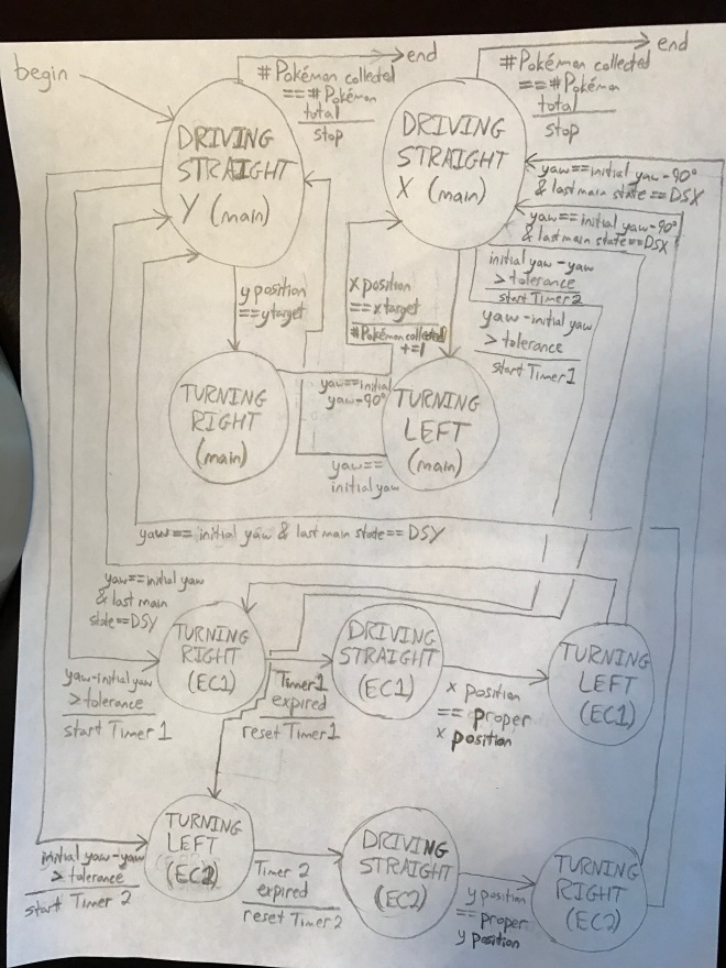
The following finite state machine diagram illustrates the behavior of the Roomba.
Notes:
- DSY indicates DRIVING STRAIGHT Y (main), DSX indicates DRIVING STRAIGHT X (main), and EC indicates ERROR CORRECTING
- In the DRIVING STRAIGHT (main) states, the Roomba can be moving forward or backward.
- “initial yaw” is the yaw at the start of the run (“begin”).
- “yaw,” “x position,” and “y position” correspond to the latest quaternion and position values received from the server.
- yaw = arctan(2.0*(x*y + z*w)/(x*x – y*y – z*z + w*w))
Results and Discussion
The Roomba can successfully catch all Pokémon no matter how many there are or where they are, as long as they are on a flat surface in the xy plane. Video A demonstrates the Roomba collecting Pokémon at locations (0,100), (50,0), and (-50,100). The initial position of the Roomba is always (0,0). When the Roomba travels over a Pokémon, it plays a musical note; this note is the same for all Pokémon except for the final one. For the trajectory shown in Video A, the data sent from the server and received on the laptop over WiFi was used for a couple of purposes. The first was to achieve 90º turns. To achieve a 90º turn, the Roomba turns until its yaw is 90º greater or less than a reference value*. Although not shown in this video, sometimes the Roomba slips and turns a bit more than 90º. The fact that the yaw values for straight line travel are referenced not to the yaw value of the most recent turn but to the yaw value at (0,0) means that the Roomba’s orientation can be easily corrected and guarantees that the accuracy of the orientation of the Roomba does not degrade during trajectories with lots of waypoints. The second way in which the server data was used was to track the spatial location of the Roomba. When the laptop received position data matching the x-coordinate and y-coordinate of a waypoint, the Roomba had collected a Pokémon and started looking for the next.
The data from the server has another important purpose. The Roomba may not drive perfectly straight line and thus it is important to correct for any deviations. A change in yaw indicates a deviation from the straight line that the Roomba should follow. When a non-negligible change in yaw occurs, the Roomba stops, turns for a bit, and moves forward until it hits the straight line again. Position data from the server is used to find this line. Then, the Roomba turns until its yaw, determined from data from the server, matches the proper yaw, and it is ready to resume normal operation. In Video B, David forces the Roomba to turn more than 90º. The system detects that the Roomba is off course, so the position error correcting algorithm kicks in and the Roomba successfully finds the correct path, not missing any Pokémon. For the small trajectories that the setup required (i.e. the small table and the fact that the PCB resting on the Roomba was tethered to the NUC), the Roomba very, very rarely wandered off course. The position error correcting algorithm would come into play much more with trajectories containing points with large distances between each other.
As long as the Hololens is set up in the orientation that it will take when it sits on the Roomba, position accuracy is high. To quantify the accuracy is difficult because the Roomba has a large diameter and the point of interest is its center. We can say with confidence that, for the trajectories that we chose, the center of the Roomba was usually within 10 mm of every Pokémon’s location. We think that our final project did quite well as a position tracking system!
*For the first turn, the end yaw value is 90º less than the start yaw value, i.e. the yaw value at (0,0). For the second turn, the end yaw value is 90º greater than the previous yaw value, or, in other words, the same as the yaw value at (0,0). For the third turn, the end yaw value is 90º less than the yaw value at (0,0). The pattern continues. So, the yaw value is either that at (0,0) or that at (0,0) minus 90º. These are the two “references values.”
