Aniq Masood, Matthew Hattori
Goal
To compare the results of our wireless motion tracking system with that implemented on the Microsoft Hololens. We built a Hololens application which drops a hologram when the user looks at it and performs a tap gesture. We control the position and orientation of the view in the scene using the wireless motion tracking system developed earlier in the course.
Hardware Setup
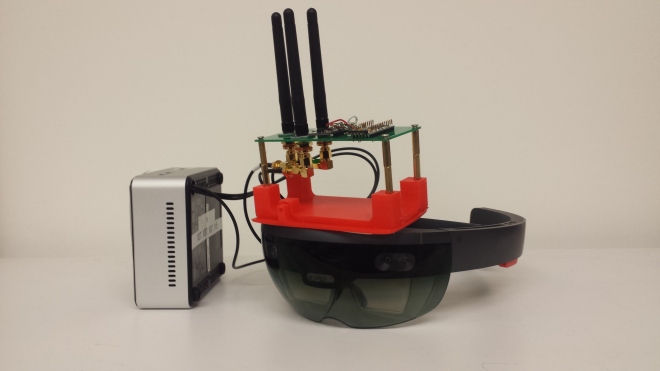
- IMU sensor board with antenna array attached to the Hololens using a 3D printed mount
- Intel NUC receives IMU data and sends to server
- Hololens will query the server for data using its built-in Wifi chip
Software Setup
- Arduino IDE for programming IMU sensor board
- Unity and Visual Studio for building the Hololens application
- Microsoft Holographic Academy Hologram 101E project example
Software/Data Processing Chain
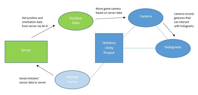
In a normal Hololens application, an augmented reality environment is created in Unity. The environment is comprised of holograms, which the user can interact with using gestures. The user’s view of the environment is dictated by the Hololens’ cameras and internal IMU sensor which track how and where the user moves.
For our project, we replaced this built-in motion tracking with our own wireless system. Our motion tracking system includes a PCB with an Arduino Pro Mini and a BNO055 IMU sensor board mounted to the top of the Hololens. The IMU sensor data (accelerometer, gyroscope and magnetometer) is sent to a server over Wifi via an Intel NUC. The server takes this data and is able to compute an estimate for position and orientation. The Hololens uses its built-in Wi-fi chip to query the server and receive this data. This position and orientation data is used by the Hololens program instead of the built-in position and orientation estimates.
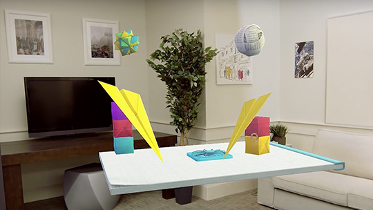
Our project is based on the Hologram 101E example project provided by Microsoft. It sets a scene with holograms that look like paper origami, as shown in Figure 2. The challenge of our project lies in the fact that by default, a Hololens project uses its internal sensors for position and gaze tracking. In the tools provided by Microsoft, there is no way to directly disable or adjust these parameters.
Our method of “hacking” the Hololens utilizes the game object structure in Unity; in a Unity application, physical objects and processes are represented as game objects in the project hierarchy. These game objects can also have their own individual hierarchy. They can be standalone objects, or objects dependent on other game objects (defined as children and parent objects).
The custom version of Unity provided by Microsoft automatically assigns the main camera object to the Hololens. To control the user’s view in the scene externally, this game object is defined as a child of another game object whose position and gaze we change.
In addition to the parent camera object, a server game object is created that retrieves the position and gaze information from the server. This game object opens a TCP client socket that sends a query to a specified port on the class server. The server acknowledges the Hololens, and returns a port number on the server that the sensor data will be broadcasted on. The socket is then closed, and another TCP client socket is created with the received port number that is continually open and retrieving information. This connection is setup on an alternate thread from the main project.
Every frame, the parent camera game object retrieves the position and gaze information obtained from the server object. It then applies position and rotation transforms in the following order:
- Set the position of the parent camera to the origin.
- Rotate the parent camera in the opposite direction of the native sensor rotation.
- Rotate the parent camera in the direction indicated by the server data.
- Set the parent camera position to the position indicated by the server data.
- Subtract the native sensor position from the parent camera position.
We found that to correctly modify the user’s position and gaze, they must be changed in the order of operations give above.
For a more accurate position estimation, the native Hololens position is sent to the server. A third game object is created that connects to the class server on an alternate port via a UDP client socket and sends the native position data.
Results
We were able to incorporate our position and orientation tracking into the Hololens application. However, we experienced a few limitations. First, there was a noticeable delay between real world movement and virtual movement in the Hololens app, unscientifically estimated at around 250 ms. Although the change in position and angle was accurate and gradual, the lag was a noticeable discomfort in the augmented reality experience.
For the orientation tracking, we experienced an issue with the range of motion. We slowly rotated the sensor board about each axis and found that after a certain angle, the gaze position in the app became sporadic. We recorded these critical angles and calculated the effective range of motion for our orientation tracking for each axis.
| Rotation | Effective Range of Motion |
| about the x-axis | ± 50 deg |
| about the y-axis | ± 130 deg |
| about the z-axis | ± 70 deg |
Incorporating the orientation tracking was more challenging than we expected, but overall it was an enjoyable learning experience. We hope that the EE107 team will build on our project in the future by making improvements to our algorithms for hacking the Hololens motion tracking. The Hololens tracking system was a lofty goal to strive for, but future iterations of this system could be very useful for VR platforms such as Samsung Gear VR and Google Cardboard. We would also recommend exploring another way of sending IMU data to the server. The NUC system we used was built off of Lab 3, but it was physically constraining because it had to be plugged into a wall outlet. A different computer, perhaps the Intel Galileo, could achieve the same functionality, but provide the Hololens user with more mobility.
